For modeling a spur gear in creo you need to have some basic data like base circle dia, Adendum, Dedendum, pitch circle dia, no. Of teeth etc.
- Do you know what is new in CREO 3.0 ? CLICK HERE
- In the last article on gear we discussed about nomenclature of gear. BASIC GEAR TERMINOLOGY
Using Relations we are going to model a gear:
1) Drawing a curve using Curve from equation.
Select the curve using equation and paste the following equations in to the notepad:
r = 2.819
ang = t * 90
s = (PI * r * t ) / 2
xc = r * cos(ang)
yc = r * sin(ang)
x = xc + ( s * sin(ang))
y = yc – ( s * cos(ang))
z = 0
Click on save and ok. Following curve would be developed in creo:

2) Now extrude a circular blank of dia 6.5mm and thickness of 1.75.

3) Collect all the basic data required to model the gear.
Sketch the base circle pitch circle, Addendum and dedendum
Here in this tutorial we would take the following values:
- Root Diameter : 5.376
- Base Diameter : 5.638
- Pitch Diameter : 6.000
Sketch the above diameter circles in creo

Now the critical point comes. How to draw the involute profile of teeth.
4) Create two datum points as below:
- Point 1: Make a datum point which is intersection of involute curve Dia 6.00mm and the curve which we made:
- Point 2: Make second point as the intersection of three planes Front, Top and Right.

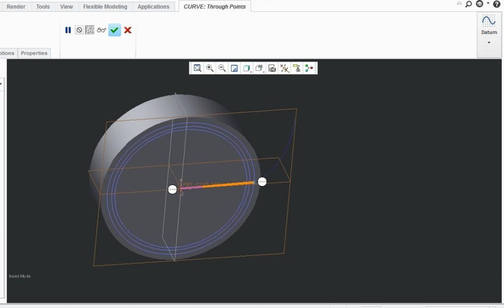
5) Draw a Curve connecting the above two datum points:
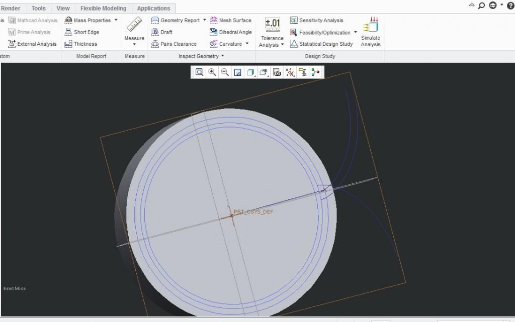
6) Insert Evaluate feature in Creo by INSERT — MODEL DATUM —– EVALUATE.
Type “Measure” as a name of the feature.
Now click on create then enter “angle” as a measurement parameter
Now you need to pick the Top datum and Curve that you created last.
Click on Done.
Save the part.
7) Copy the Involute curve by -30 degree angle. You will get the new copied curve as below.

Double click the 30° angle and carefully enter
: angle:FID_MEASURE + ( 7.5 / 2 )
Click YES to enter the relation
Note : If you can’t use the above feature then.
You have to enable the config option allow_anatomic_features8) Mirror the Copied Curve taking the top datum surface as reference to it.
9) Move the copied involute curve
Click edit then Copy.
Click on Edit then Paste Special
Click on check box of “Apply Move/Rotate transformations to copies” then click OK
Now click on Rotate in the popup menu taking axis of the cylinder and -15° as the rotation angle. U’ll get the following result:

your involute curve for gear tooth is generated
10) Extrude cut the teeth as the section below.

11) Pattern the extrude cut feature by taking axis of the gear.
Enter 24 as number of pattern and 15° increment angle.

12) Finally Extrude cut a hole of Dia Ø2 from center.

Hola your gear is designed.
For reference you can download the above model :
CLICK HERE